倒角
参考
模式
编辑模式
菜单
边 ‣ 边线倒角
快捷键
Ctrl-B
菜单
网格 ‣ 顶点 ‣ 顶点倒角 (仅适用于顶点)
快捷键
Shift-Ctrl-B (仅适用于顶点)
The Bevel tool allows you to create chamfered or rounded corners on geometry. A bevel is an effect that smooths out edges and corners.
Real world edges are very seldom exactly sharp. Not even a knife blade edge can be considered perfectly sharp. Most edges are intentionally beveled for mechanical and practical reasons.
倒角同样有助于为非自然模型赋予真实感。在现实世界中,物体的钝边吸收光线,并改变棱边四周的着色效果。与看上去过于完美的无倒角物体相反,这带来了种实体的、真实的观感。

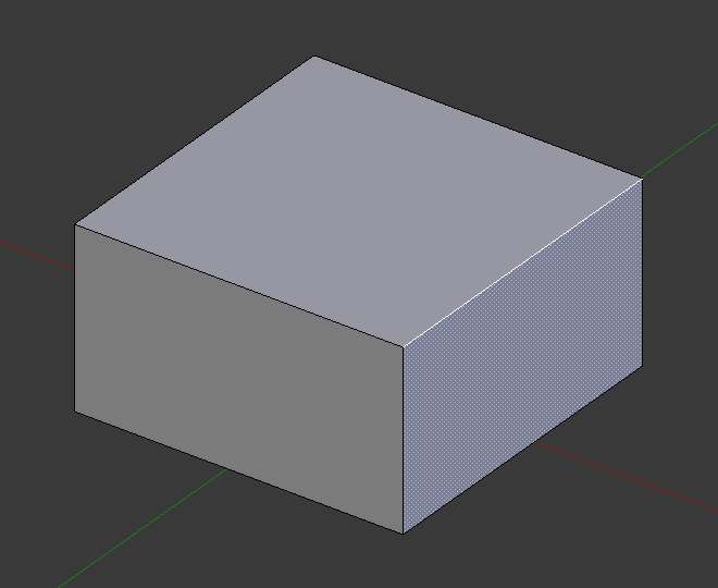
倒角和无倒角的方块。
用法
The Bevel Edges tool works only on selected edges with exactly two adjacent faces. It will recognize any edges included in a vertex or face selection as well, and perform the bevel the same as if those edges were explicitly selected. In “vertex only” mode, the Bevel Vertices tool works on selected vertices instead of edges, and there is no requirement about having any adjacent faces. The Bevel tool smooths the edges and/or “corners” (vertices) by replacing them with faces making smooth profiles with a specified number of segments (see the options below for details about the bevel algorithm).
Use Ctrl-B or a method listed above to run the tool. Move the mouse to interactively or type a number to specify the bevel offset, and scroll the Wheel to increase or decrease the number of segments (see below).
 倒角之前的选中边。 | 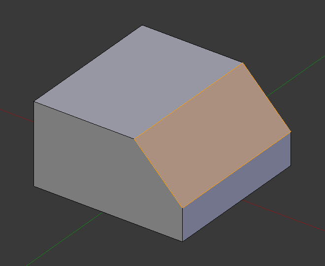 倒角结果(1段)。 |  倒角结果(仅顶点)。 |
Note
常规(边线)倒角仅适用于与两个面相邻的边。顶点倒角则没有这些限制。
选项
量级类型 A
用户可以通过移动鼠标,使其靠近或远离物体,来改变倒角的量。该值的准确意义取决于 量级类型 (见下文)。和平常一样,可以通过同时按下 Shift 来调整影响程度为 0.001,来获得更加精细的结果。 LMB 结束操作, RMB 或 Esc 中止操作。
量级类型 M
用于选择 数量 对倒角程度的计算方式,对应的类型有:
偏移量
新边线到原始连线的距离。
宽度
倒角面宽度。
深度
原始边到倒角面的垂直距离。
百分比
新边线滑移距离相对邻边长度的百分比。
For vertex-only bevels, the Offset and Depth types measure from the original vertex, and the Width type is measured from a new vertex to the center of the new face (as half the amount).
段数 S
滚动 Wheel 增加或减少倒角面段数。段数越多,倒角越平滑。也可以按下 S ,移动鼠标或输入数值来改变段数。
另外,在使用该工具时或结束操作后的操作面板上,可以手动输入段数值。
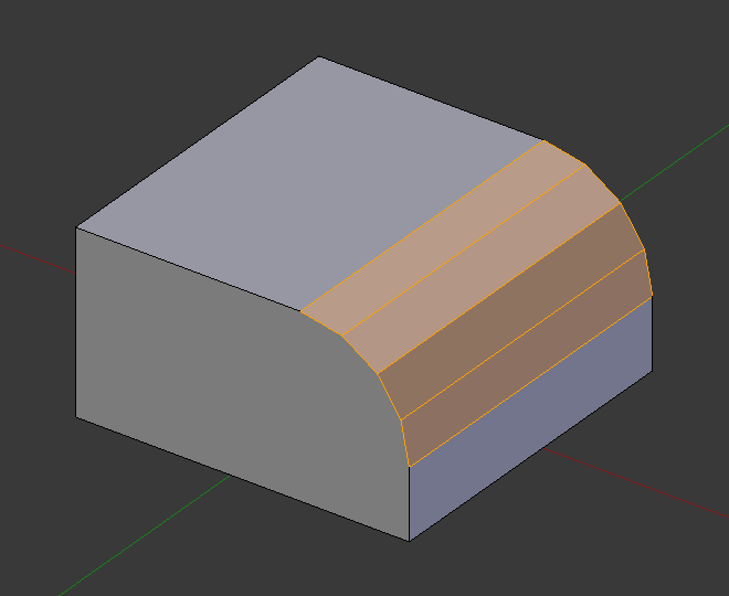
段数为4的倒角。
轮廓 P
大小介于0到1,用于控制倒角的轮廓(倒角边侧视)形状。默认值为0.5,轮廓为圆弧形(如果这些面以正确的角度相连)。低于该值,轮廓变得平坦,0.25为平面,低于0.25为内凹的倒角。该值大于0.5,倒角面更加突出。与 段数 类似,该值可以在按下 P 后移动鼠标或输入数值修改。
仅顶点 V
勾选后,使用 “仅顶点模式”,仅对每个顶点倒角。
限制重叠 C
Limits the width of each beveled edge so that edges cannot cause overlapping intersections with other geometry.
环切线滑移
如果有其他不参与倒角的边与倒角边通过同一个顶点,倒角面会尽可能沿着这些边滑动(维持这些非倒角边的位置)。启用该选项可以获得更加均匀的倒角宽度。
标记缝合线 U
If a seam edge crosses a non-seam one and you bevel all of them, this option will maintain the expected propagation of seams.
Mark Sharp K
Similar to Mark Seams, but for sharp edges.
材质
材质 编号用于指定赋予新 倒角 面的材质,默认为-1,继承最近的现有面的材质(“最近” 似乎有些含糊)。否则,将为新的倒角面赋予材质槽中对应编号的材质。
Harden Normals H
When enabled, the per-vertex face normals of the bevel faces are adjusted to match the surrounding faces, and the normals of the surrounding faces are not affected. This will keep the surrounding faces flat (if they were before), with the bevel faces shading smoothly into them. For this effect to work, custom split normals need to be enabled, which requires Auto Smooth to be enabled (see Normals). As a convenience, that option will be enabled for you if it is not already when you enable Harden Normals here.
Face Strength Mode
Set Face Strength on the faces involved in the bevel, according to the specified mode. This can be used in conjunction with a Weight Normals Modifier (with the Face Influence option checked).
None
Do not set face strength.
New
Set the face strength of new faces along edges to Medium, and the face strength of new faces at vertices to Weak.
Affected
In addition to those set for the New case, also set the faces adjacent to new faces to have strength Strong.
All
In addition to those set for the Affected option, also set all the rest of the faces of the model to have strength Strong.
Outer Miter O
A miter is formed when two beveled edges meet at an angle. On the side where the angle is greater than 180 degrees, if any, it is called an outer miter. This option specifies the pattern that Blender uses at an outer miter.
Sharp
Edges meet at a sharp point, with no extra vertices introduced on the edges.
Patch
Edges meet at a sharp point but in addition, two extra vertices are introduced near the point so that the edges and faces at the vertex may be less pinched together than what occurs in the Sharp case. The Spread slider controls how far the new vertices are from the meeting point.
Arc
Two vertices are introduced near the meeting point, and a curved arc joins them together. The Spread slider controls how far the new vertices are from the meeting point. The Profile slider controls the shape of the arc.
The current choices are shown in this diagram, where the outer miter is along the horizontal surface.
 Sharp outer miter. | 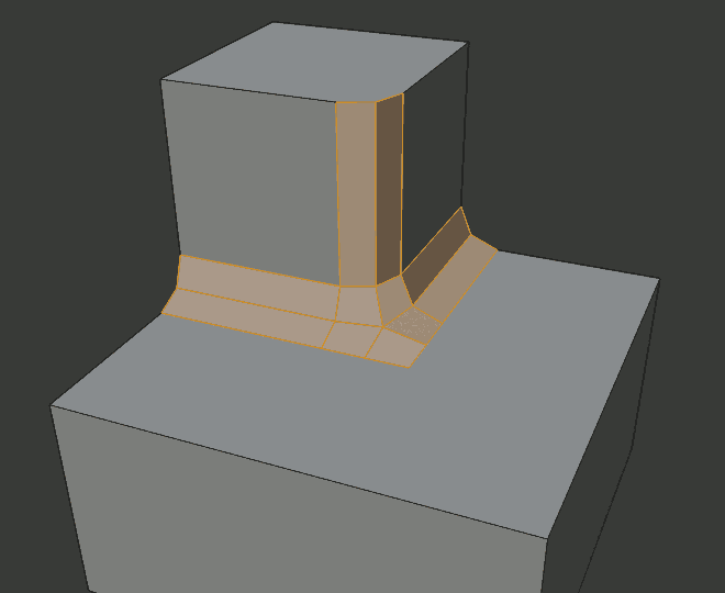 Patch outer miter. | 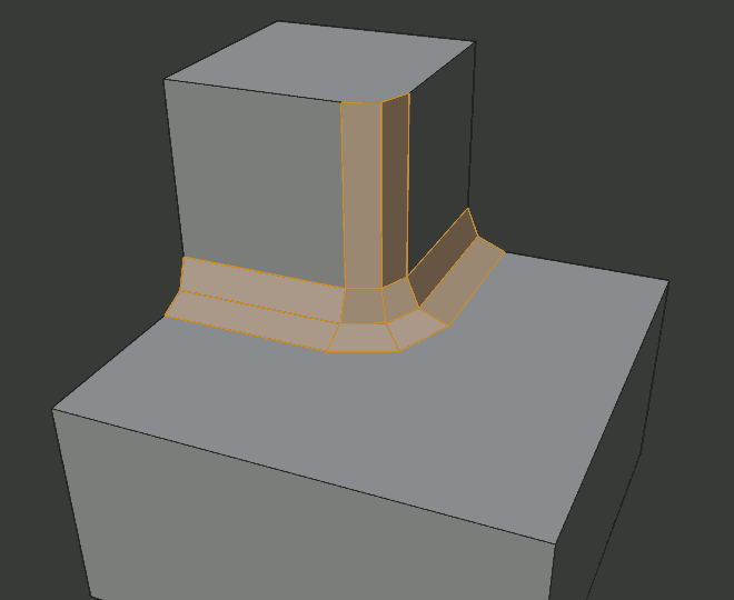 Arc outer miter. |
Inner Miter I
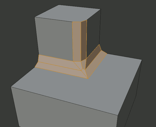
An Inner Miter is formed when the angle between two beveled edges is less than 180 degrees. This option specifies the pattern Blender uses at an inner miter. The options are the same as for Outer Miter, except that Patch makes no sense and is therefore omitted. Inner miters are shown in the following diagram, where two inner miters are on the vertical surfaces.
 Sharp inner miter. | 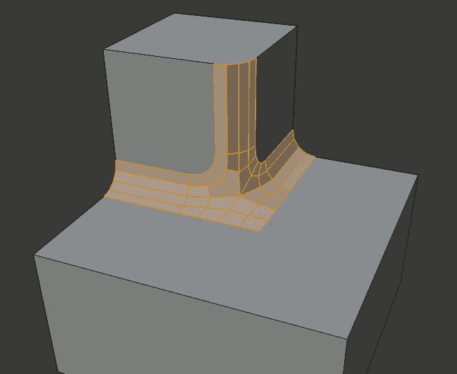 Arc inner miter. |
Spread
The value used to spread extra vertices apart for Outer and Inner Miters.
Intersection Method N
When more than two beveled edges meet at a vertex, a mesh is created as a way to complete the intersection between the generated geometry. This option controls the method used to create that mesh.
Grid Fill
The default method for building intersections, useful when a smooth continuation of the bevel profile is desired. Without Custom Profile enabled, the curve of the profile continues through the intersection, but with a custom profile it just creates a smooth grid within the intersection’s boundary.
Cutoff
Creates a cutoff face at the end of each beveled edge coming into the vertex. This is most useful for custom profiles when the new intersection is too complex for a smooth grid fill.
With a three way intersection, when the inner corners of the cutoff profiles faces meet at the same location, no center face is created.
The direction of the cutoff faces depends on the original vertex’s normal.
 Grid fill intersection method. | 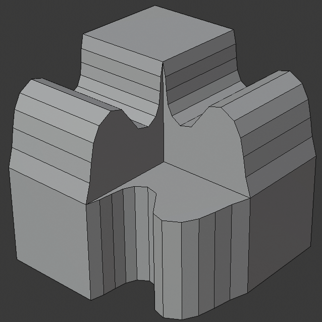 Three way cutoff intersection where the inner vertices are merged. | 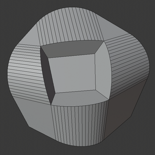 Cutoff intersection method with a center face. |
Custom Profile Z
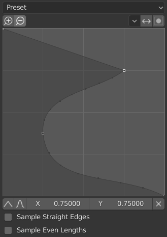
The custom profile widget.
This widget allows the creation of a user-defined profile with more complexity than with the single profile parameter. The modal tool allows toggling the custom profile, but the shape of the profile is only editable in the options panel after the operation is confirmed.
The profile starts at the bottom right of the widget and ends at the top left, as if it were between two edges meeting at a right angle. Control points are created in the widget and then the path is sampled with the number of segments from the bevel modifier.
Presets
The Support Loops and Steps presets are built dynamically depending on the number of segments in the bevel. If the number of segments is changed, the preset will have to be re-applied.
Reverse
The Reverse button flips the orientation of the profile for all beveled edges.
Clipping
The Clipping toggle allows control points to be moved beyond the initial boundary, allowing the bevel to add volume to the mesh rather than just removing it.
Note
The Profile slider is still useful when miters are enabled because it still controls the shape of the miter profiles.
Sampling
Samples will first be added to each control point, then if there are enough samples, they will be divided evenly between the edges. The Sample Straight Edges option toggles whether the samples are added to edges with sharp control points on either side. If there aren’t enough samples to give each edge the same number of samples, they will just be added to the most curved edges, so it is recommended to use at least as many segments as there are control points.
范例
 多条边同时倒角。 |  另一个多条边同时倒角的例子。 | 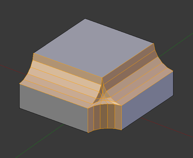 轮廓值=0.150的倒角结果。 |
See also
倒角修改器
倒角修改器 是倒角工具的非破坏版本。