倒角修改器
倒角 修改器可以把应用该修改器的网格的棱切成斜角,允许控制如何以及哪里把倒角操作应用到网格上。
倒角修改器是编辑模式下 倒角操作 的非破坏替代。
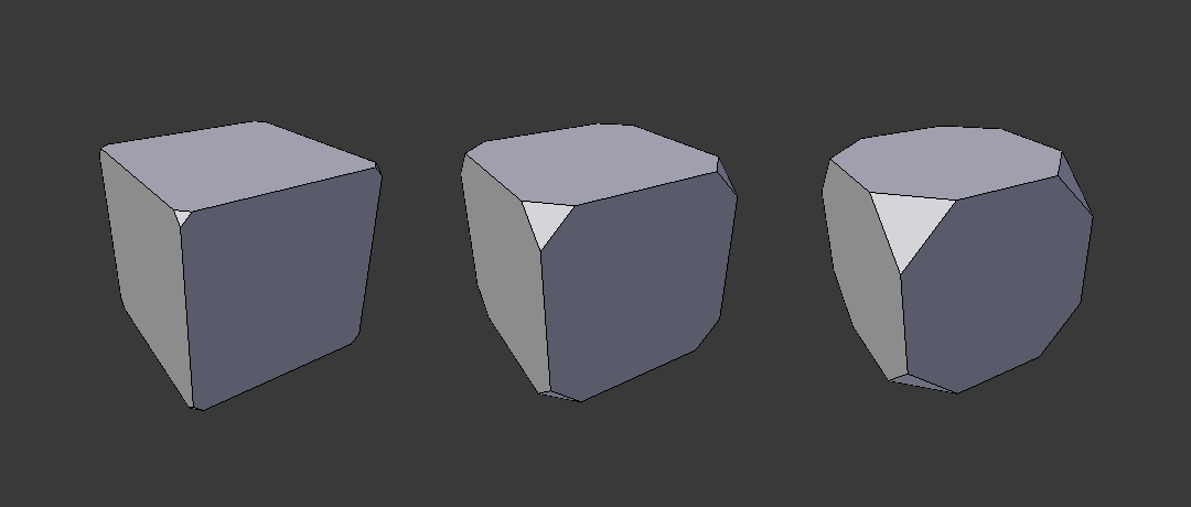
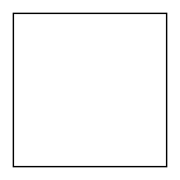 未倒角。 | 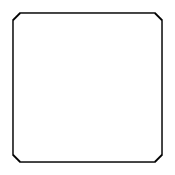 已倒角。 |
选项
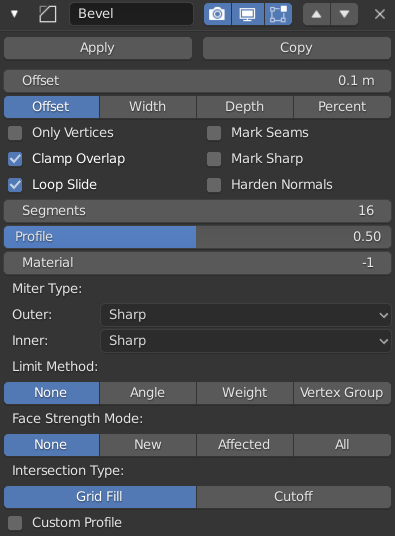
倒角修改器。
宽度
倒角影响的尺寸,见下面的 宽度方法 。
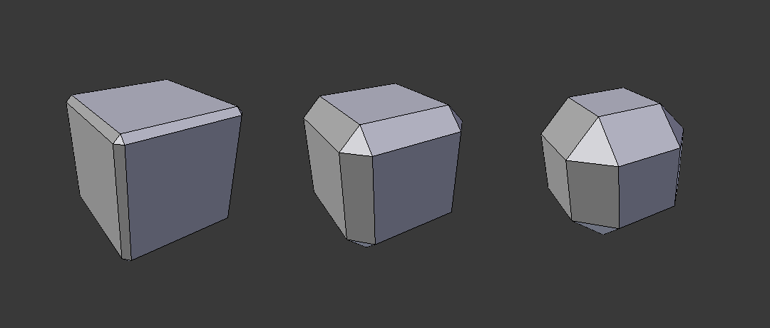
三个倒角宽度分别为 0.1、0.3 和 0.5 的立方体。
段数
沿着倒角面所添加环边的数量。
轮廓
倒角的形状,从凹到凸——如果 段数 少于2则无效果。
材质
用来倒角的材质槽的索引。当设置为 -1 时,将采用最靠近原始面的材质。
仅顶点
启用该选项时,仅靠近顶点的区域会倒角,边不受倒角影响。
三个倒角宽度分别为 0.1, 0.3 和 0.5 的立方体,启用了 仅顶点 选项。
钳制重叠
限制每个倒角边的宽度,使边缘不能与其他几何图形重叠。
环切线滑移
如果一个顶点有未倒角的边和已倒角的边,倒角会尽可能沿着这些边滑动。关闭该选项可以导致更均匀的倒角宽度。
标记缝合边
如果一个缝合边穿过一个非缝合边,并且你把所有的边都进行倒角,这个选项将保持缝合边按预期延伸。
标记锐边
类似于标记缝合边,但是是为锐边设置的。
硬化法向
启用后,将调整倒角面的每个顶点面法线以匹配周围的面,并且不影响周围面的法线。这将使周围的面平坦(如果以前是面),使倒角面阴影光滑。要实现这种效果,需要自定义法线数据,这需要启用 自动光滑 选项(参见 法线 )。
限定方式
用来控制对网格应用倒角的位置。
无
无限制,所有的棱将会倒角。
角度
邻接面构成的二面角小于定义的阈值的棱将会倒角。用来允许你仅对物体构成尖端的棱倒角,而不影响光滑的表面。
权重
使用每个边的倒角权重来确定倒角的宽度。当倒角权重取 0.0 时,不会应用倒角。请参考 这里 了解关于调整倒角的权重。
顶点组
用一个顶点组的权重,来确定该倒角面的宽度。当倒角权重取0.0时,不会应用倒角。两个顶点都在顶点组的棱才会倒角。请参考 这里 了解关于调整顶点组的权重。
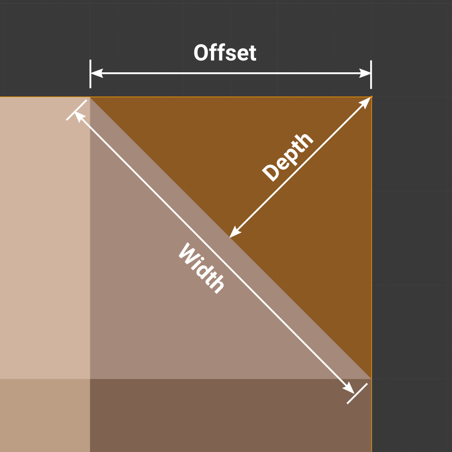
宽度方法
声明如何使用 宽度 以决定倒角总数.
宽度方法.
偏移量
该值被解释为从原始边缘到被倒角的面的边缘的距离。
宽度
该值被解释为倒角产生的两个新边之间的距离。
深度
该值是从原始边到倒角面的垂直距离。
百分比
与 偏移量 类似,但该值被解释为相邻边长的百分比。
设置面强度模式
根据这里指定的模式,在倒角所涉及的面上设置 面强度 。这可以与以下修改器一起使用 加权法向修改器 (勾选 面影响 选项)。
无
不设置面强度。
新建
设置沿边缘的新面的面强度为 中 ,顶点的新面的面强度为 弱 。
受影响的
除了为设置为 新建 的那些面外,还将相邻的面设置为具有 强 强度。
全部
除了那些设置为 受影响的 情况,还设置模型的所有其余面强度是 强 。
斜接模式
当两个倒角边以一定角度相交时,就形成了 斜接 。如果有的话,在角大于180度的一侧,称为 外斜接 。如果小于180度,则称为 内斜接 。外斜接和内斜接可以分别设置为以下模式之一:
锐边
边在一个尖锐点相遇,且边上没有额外的顶点。
补块
边在一个尖锐的点相交,但是除此之外,在这个点附近引入了两个额外的顶点,这样顶点上的边和面就不会像在 尖锐 情况下那样被挤在一起。这种模式对于内斜接没有任何意义,因此它的行为类似于 圆弧 。
扩展滑块控制新顶点到交点的距离。
圆弧
在交点附近引入两个顶点,然后用一条弧线将它们连接在一起。
扩展滑块控制新顶点到交点的距离。
轮廓 滑块控制圆弧的形状。
 锐边外斜接 | 补块外斜接 | 圆弧外斜接 |
锐边内斜接 | 圆弧内斜接 |
扩散
该值用于控制非锐边斜接引入的顶点的分散程度。
Intersection Method
When more than two beveled edges meet at a vertex, a mesh is created as a way to complete the intersection between the generated geometry. This option controls the method used to create that mesh.
Grid Fill
The default method for building intersections, useful when a smooth continuation of the bevel profile is desired. Without Custom Profile enabled, the curve of the profile continues through the intersection, but with a custom profile it just creates a smooth grid within the boundary of the intersection.
Cutoff
Creates a cutoff face at the end of each beveled edge coming into the vertex. This is most useful for custom profiles when the new intersection is too complex for a smooth grid fill.
With a three way intersection, when the inner corners of the cutoff profiles faces meet at the same location, no center face is created.
The direction of the cutoff faces depends on the original vertex’s normal.
 Grid fill intersection method. | 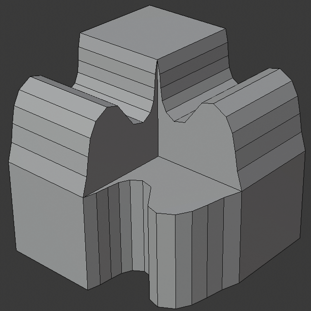 Three way cutoff intersection where the inner vertices are merged. | 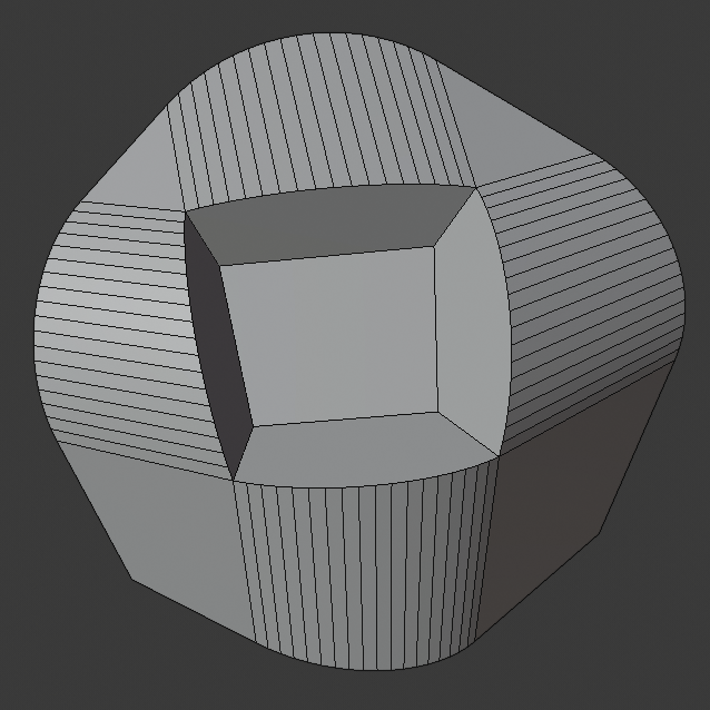 Cutoff intersection method with a center face. |
Custom Profile
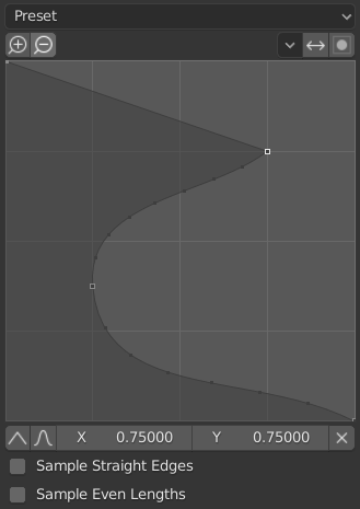
The custom profile widget.
This widget allows the creation of a user-defined profile with more complexity than with the single profile parameter. The modal tool allows toggling the custom profile, but the shape of the profile is only editable in the options panel after the operation is confirmed.
The profile starts at the bottom right of the widget and ends at the top left, as if it were between two edges meeting at a right angle. Control points are created in the widget and then the path is sampled with the number of segments from the bevel modifier.
Presets
The Support Loops and Steps presets are built dynamically depending on the number of segments in the bevel. If the number of segments is changed, the preset will have to be re-applied.
Reverse
The Reverse button flips the orientation of the profile for all beveled edges.
Clipping
The Clipping toggle allows control points to be moved beyond the initial boundary, allowing the bevel to add volume to the mesh rather than just removing it.
Note
The Profile slider is still useful when miters are enabled because it still controls the shape of the miter profiles.
Sampling
Samples will first be added to each control point, then if there are enough samples, they will be divided evenly between the edges. The Sample Straight Edges option toggles whether the samples are added to edges with sharp control points on either side. If there aren’t enough samples to give each edge the same number of samples, they will just be added to the most curved edges, so it is recommended to use at least as many segments as there are control points.