简介
有很多选择网格元素的方式,而且可以使用什么样的选择工具还取决于您当前在什么 网格选择模式 下。首先我们简要了解一遍这些选择模式,然后将对基础的选择工具稍作了解。
选择模式
参考
模式
编辑模式
菜单
3D视图标题栏 ‣ 选择模式
热键
1, 2, 3 (Shift 多选择模式, Ctrl 扩展/缩减选择)。
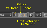
编辑模式选择按钮。
在 编辑模式下 有三种不同的选择模式。您可通过选择标题栏中三个按钮中的某个来进入不同的选择模式。
顶点
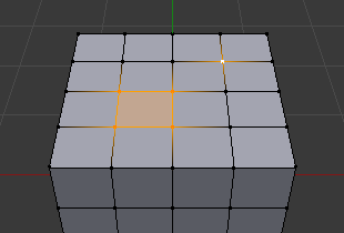
In this mode vertices are shown as points. Selected vertices are displayed in orange, unselected vertices in black, and the active or last selected vertex in white.
边
In this mode the vertices are not shown. Instead the selected edges are displayed in orange, unselected edges black, and the active or last selected edge in white.
面
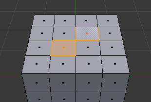
In this mode the faces are displayed with a selection point in the middle which is used for selecting a face. Selected faces and their selection point are displayed in orange, unselected faces are displayed in black, and the active or last selected face is highlighted in white.
当使用这些按钮时,可充分利用编辑键,详见: 切换选择模式。
几乎所有的工具都可以在全部的三种选择模式下使用。所以您在所有的模式下都可以 旋转 , 缩放 , 挤出 等。当然,对单个 顶点 进行旋转和缩放是没有意义的(除非 将原点设在了另一个位置),所以某些工具在某些选择模式下可能更加适用或不太适用。
不同选择模式示例详见参考图 选择模式。 。
多选择模式
By holding Shift-LMB when selecting a selection mode, you can enable multiple Selection Modes at once. This allows you to quickly select vertices, edges, or faces, without first having to switch mode.
 点选择模式示例。 | 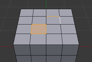 边选择模式示例。 |
 面选择模式示例。 | 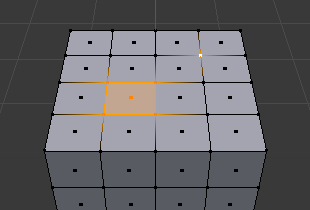 混合选择模式示例。 |
切换选择模式
当以“升级”的方式(换句话说就是由简单走向复杂)切换选择模式,从 顶点 切换到 边 以及从 边 切换到 面,如果选中元素能构成新的选择模式下的完整元素,其将保持选中状态。
例如,如果一个面上所有四条边都被选中,由 边 选择模式切换到 面 选择模式下将会保持其构成的面处于被选中状态。所有未能够构成新选择模式下完整元素的内容将被弃选。
边选择模式,初始选择。 | 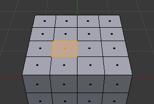 切换到面选择模式。 |
因此,以“降级”的方式(换句话说就是由复杂走向简单)切换选择模式,所有定义“高级”元素(比如面)的元素将仍然处于选中状态(比如四边形的四个顶点或四条边)。
扩展/缩减选择
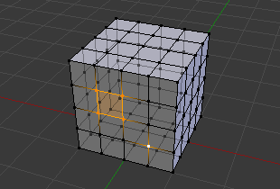
By holding Ctrl when selecting a higher selection mode, all elements touching the current selection will be added, even if the selection does not form a complete higher element. Or contracting the selection when switching to a lower mode.
顶点选择模式,初始选择。 | 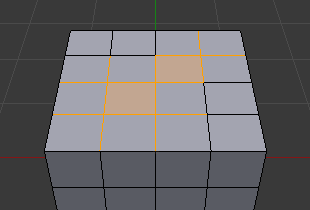 扩展边模式。 |
透视
The x-ray setting is not just for shading, it impacts selection too. When enabled, selection isn’t occluded by the objects geometry (as if the object was solid).
 透视打开。 | 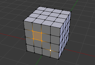 透视关闭。 |
选择菜单
全部 A
全部选择。
无 Alt-A
取消选择。
反转 Ctrl-I
选择全部未选中网格,并对当前已选中对象取消选择。
框选 B
交互式框选。
刷选 C
交互式刷选。
根据百分比随机选择一组顶点、边或面。
从当前活动项开始间隔性地取消选择数个元素。
选择锐边
该工具选择所有相邻面构成夹角大于一定角度值的边,给定角度值越大选中的边越尖锐。
选择相似 Shift-G
选择与当前选中元素相似的元素。
通过查询对象特征以选择网格。
扩展选择/缩减选择
扩展选区 Ctrl-数字键盘+
扩展到当前选择模式下与选中区域相连的区域。
缩减选区 Ctrl-数字键盘-
从当前选择模式下选中区域相连的部分缩减选择。
下一活动元素 Shift-Ctrl-NumpadPlus
This uses selection history to select the next vertex, edge, or face based on surrounding topology.
上一活动元素 Shift-Ctrl-NumpadMinus
选择前一活动元素并取消对最后选择元素的选择状态。
选择循环
选择相连元素
-
Selects all components that are connected to the current selection.
两个元素之间的最短路径。
相连的平展面
按面与面的夹角阈值选择相连面。该功能对于选择平整的面片相当有用。
选择活动项的同侧
选择网格上与活动顶点处于相同单一轴向上的所有顶点。仅限于顶点选择模式。
镜像选择 Shift-Ctrl-M
选择指定轴向上镜像位置的元素。
已知问题
密集网格
Selecting dense meshes with X-Ray disabled, has a limitation where dense meshes may not have all the elements selected. When selecting regions with Box, Circle and Lasso select, vertices may overlap each other causing some vertices not to be selected. This is a limitation with the current selection method, you may workaround this by zooming in or enabling X-Ray.
面选择模式下的N边形面

中心点在其他面上的N边形面。
As already noted, in X-Ray and Wireframe mode faces are marked with a dot in the middle. With n-gons that can lead in certain cases to a confusing display. The example shows the center dot of the U-shaped n-gon being inside of the oblong face inside the “U”. It is not easy to identify which dot belongs to which face (the orange dot in the image is the object origin).