切割
参考
模式
编辑模式
工具
工具栏 ‣ 切割
快捷键
K
切割工具可用于通过绘制线条细分(切断)几何体,或切开闭合循环,制造空洞。
用法
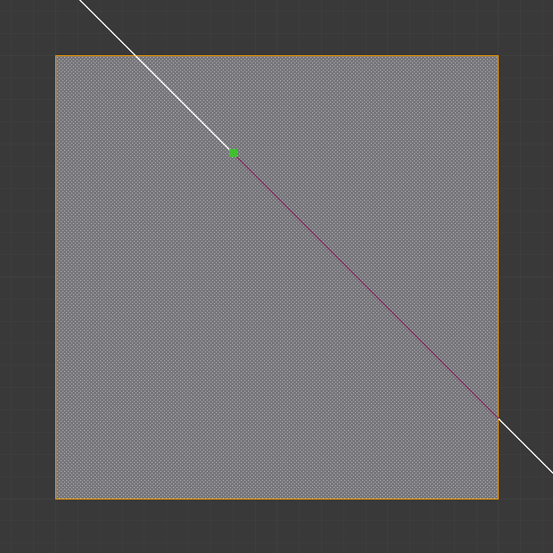
当使用 切割 时,光标会变成手术刀的图标,标题栏变化为显示该工具的选项。您可以通过按下 LMB 来绘制连续的线段,端点用绿色小方块标记。已定义的切割点显示为红色小方块。带有框线的红色小方块表示该位置已经有一个切割点,所以不会再创建额外的顶点(除了第一个顶点)。
If multiple objects are selected before entering Edit Mode, then knife cuts will affect all of those objects.
 切割前网格。 | 激活切割工具。 | 确认切割后。 |
工具设置
遮蔽几何体
仅切割屏幕可见的几何体部分。
Only Selected Shift-K
仅切割所选的几何体部分。
透视
Show cut points on non-visible geometry too, when Occlude Geometry is deactivated.
测量
Which visible measurements to show.
Distance, Angle, None, Both
Angle Snapping
Whether or not dragged lines should be constrained to particular angles, and if so, which coordinate system the angle is relative to.
None, Screen, Relative
Angle Snapping Increment
When angle snapping is on, the angle will be constrained to a multiple of this angle.
控制器
Confirm Spacebar or Return
使用 Return 确认切割,这将保留选中的每一条边,除了从切割中创建的新边。
取消 Esc
Cancels the cut.
绘制一条连续的线段 拖动 LMB 。
所以你可以在表面手绘一条直线,与边线相交位置会自动创建端点。
闭合切线 双击 LMB
闭合当前切线的便捷方法。
New Cut RMB
开始新的切割,用于定义多条不同的切割线。如果已经定义了多条切割线,会将其识别为新的吸附点。
创建多条切割线。 | 切割效果。 |
Midpoint Snap Shift
按住后吸附游标至边线中点,这样产生的所有切点都正好位于边线的中点。
Ignore Snap Ctrl
按住后忽略吸附,不同于默认的吸附至最近边。
Cut Through: C
Allow the Cut tool to cut through to occluded faces, instead of only the visible ones.
Angle Constrain A
Constrains the cut line to certain degree increments. The increment can be specified in the Tool Settings (see above), or can be typed when angle constraining is active. The default angles are in the plane of the screen, but typing A again makes it relative to the last cut edge. If the last cut edge is ambiguous (because the cut was on a vertex), typing R cycles through the possible reference edges.
 限制切线角度。 | 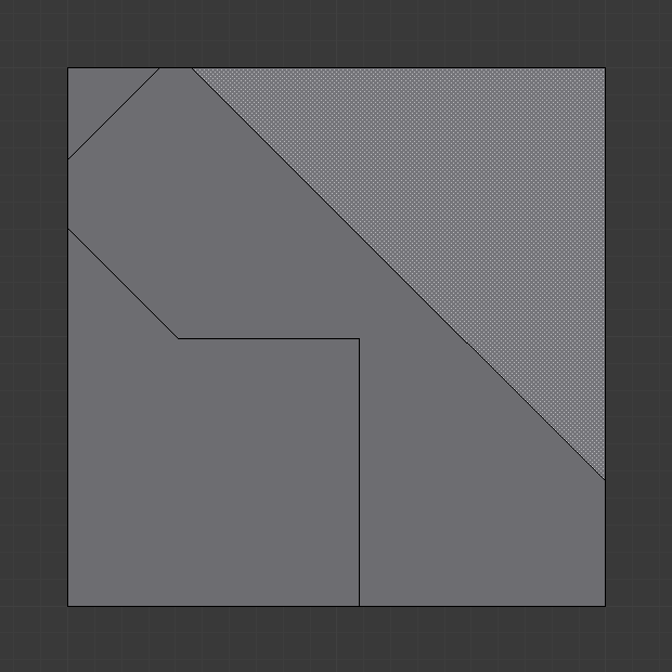 限制角度的结果。 |
Axis Constrain X, Y, or Z
Constrains the cut line to one of the coordinate system axes. Initially it will be the global axis with the given name, but pressing the same key again switches to the object’s local axis system. Additionally, if the scene transformation orientation is set to a custom orientation (e.g. from a face), the constraints will be in that coordinate system.
Visible Measurements S
Shows measurements of the cuts being made: angles with respect to a mesh edge, lengths, or both. Pressing S repeatedly cycles between what can be shown.
Only Distance, Only Angles, Both, None
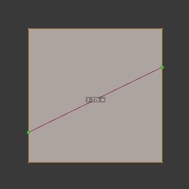 Only Distance. | 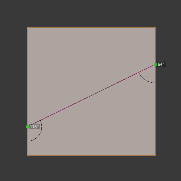 Only Angles. |  Both Angles and Distance. |
Undo Ctrl-Z
Undoes the previous cut segment. The starting point for the next cut is adjusted accordingly. If a cut is a drag cut, the entire drag cut is undone.
X-Ray Mode V
Toggles whether or not cuts to segments behind the visible geometry are shown.
已知局限
复制顶点
如果遇到了切割后生成重复顶点的问题,这通常是由于远/近可视范围过大的缘故。
试试调高 起始可视范围 来避免该问题,详情参考 深度排错。
未连接的切线
起点或终点位于面中间的切线将被忽略。
该工具受限于Blender可以表达的几何元素类型。