几何数据(Geometry)

几何面板。
偏移量
将挤出平行于曲线法线移动。
偏移量 -1,挤出 0.5,倒角深度 0.25,倒角分辨率 10 的贝塞尔圆。
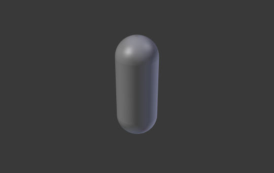
挤出
将沿着正负Z轴挤出曲线。通过赋予一维曲线高度,将其转化为二维曲线。该尺度是两个方向的和,挤出物垂直于曲线的法线。
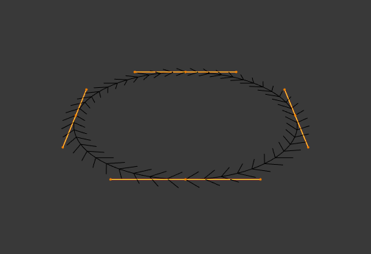 挤出0.0的贝塞尔圆 (编辑模式)。 | 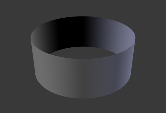 挤出0.5 (物体模式)。 |
锥化物体
Tapering a curve causes it to get thinner towards one end. You can also alter the proportions of the Taper throughout the tapered object by moving/scaling/rotating the control points of the Taper Object. The taper curve is evaluated along the local X axis, using the local Y axis for width control. In order for this to work the Taper Object can only be another open curve.
The details are:
锥化物体独立应用于被挤出物体的所有曲线。
只计算 锥化物体 中的第一条曲线, 即使锥化物体包含多条断开的线段。
缩放从左侧的第一个控制点开始,并沿曲线向右侧的最后一个控制点移动。
负值缩放,(在锥化曲线上的局部坐标系负Y轴) 也是可能存在的。但是, 可能会出现渲染伪影。
You may need to increase the curve resolution to see more detail of the taper.
The Taper Object is distributed by control points. Therefor unevenly spaced control points may likelier to stretch the shape of the taper. Subdividing segments causes those points to use a larger fraction of the overall taper shape.
在闭合曲线下, 锥化物体 中的锥化曲线作用于整个曲线(物体的周长),而不仅仅是物体的长度,并改变挤出深度。在这些情况下,您希望 锥化物体 锥化曲线两端的相对高度相同,以便循环点(曲线末端点与起点连接的地方)是一个平滑的过渡。
Hint
Editing the handles and control points of the Taper Object will instantly change the shape of the original object.
Taper Mode
For curves using a Taper Object, this option defines how the effective curve radius is computed from the Taper Object.
覆盖
The curve radius is ignored and the effective radius is equal to the taper radius.
正片叠底(相乘)
The effective radius is computed by multiplying the taper radius with the curve radius.
相加
The effective radius is computed by adding the taper radius to the curve radius.
Override mode. | Multiply mode. | Add mode. |
映射锥化
对于使用锥化物体并修改了 倒角起点/终点系数 的曲线, 映射锥化 用于使锥化仅作用于曲线的被倒角范围 (而非整条曲线) 。
倒角
圆(四舍五入)
深度
改变倒角的尺寸。
 A curve with different Bevel depths applied (Depth of 0.05). | 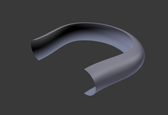 A curve with different Bevel depths applied (Depth of 0.25). |
分辨率
调整倒角的平滑度。
 A curve with different resolutions applied (Resolution of 1). | A curve with different resolutions applied (Resolution of 12). |
填充封盖
封住倒角曲线两端。
物体
物体
Here you can specify a curve object (opened or closed) which will be extruded along the curve. If your object’s shape is 3D, it will be projected to its local XY plane before the extrusion. You can check how the projected Object looks like by switching its shape to 2D.
Important
Make sure the shape you want to extrude is in the Object’s local XY plane. If it is in the local XZ or YZ plane, it will be reduced to a line when it is projected to the local XY plane. Because of this, the extruded shape will be a flat plane.
 A curve with a Bézier curve as the Bevel Object. | 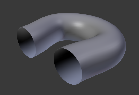 A curve with a Bézier circle as the Bevel Object. |
轮廓
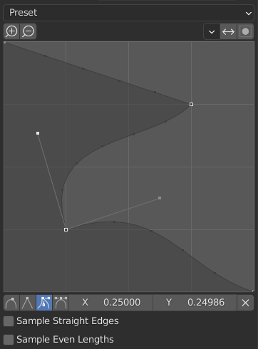
自定义轮廓控件。
此控件用于创建用户定义的轮廓,其复杂性比使用单个轮廓参数更复杂。模态工具允许切换自定义轮廓,但仅在确认操作后,才能在选项面板中编辑轮廓形状。
The profile starts at the bottom right of the widget and ends at the top left, as if it were between two edges intersecting at a right angle. Control points are created in the widget and then the path is sampled with the number of segments from the Bevel modifier.
Note
The Profile slider stays active when miters are enabled because it still controls the shape of the miter profiles.
预设
支撑环 和 阶梯* 预设根据斜角中的段数动态生成。如果段数发生更改,则必须重新应用预设。
采样
Samples will first be added to each control point, then if there are enough samples, they will be divided evenly between the edges. The Sample Straight Edges option toggles whether the samples are added to edges with sharp control points on either side. If there aren’t enough samples to give each edge the same number of samples, they will just be added to the most curved edges. So it is recommended to use at least as many segments as there are control points.
开始 & 结束映射
Factor Start, End
These options determine where to start/end the geometry of the curve. This allows to make a curve which is not fully covered with geometry.
将 倒角起点系数 改为0.5 ,将从距离曲线起点50% 的距离开始倒角 (实际上缩短曲线)。将 倒角终点系数 改为降低0.25,将从距离曲线终点25% 的距离开始倒角(再次缩短曲线)。
A curve with no Factor Start, End. | 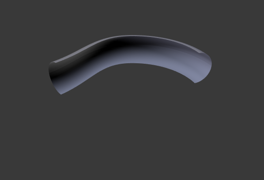 A curve with a 0.6 End factor. |
Mapping Start, End
Allows to control the relation between the Factor Start, End (number between 0 and 1) and the rendered start and end point of the spline’s geometry.
分辨率
Maps the start and end factor to the number of subdivisions of a spline (U resolution).
段数
Maps the start and end factor to the length of its segments. Mapping to segments treats the subdivisions in each segment of a curve as if they would have all the same length.
样条线
Maps the start and end factor to the length of a spline.
示例
开放的2D曲线
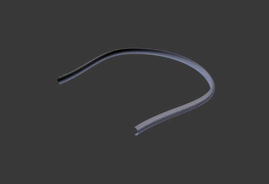
挤出将沿曲线形状创建一面“墙”或一条“带子”。如果使用了 倒角深度 , 则墙将变得类似滑梯或者槽子。如果法线朝向错误,可以按照 这里 的操作切换方向。
Alt-C 将2D曲线变成开放的,填充设为无,偏移量为0,挤出0.5,倒角深度0.25,倒角分辨率10。
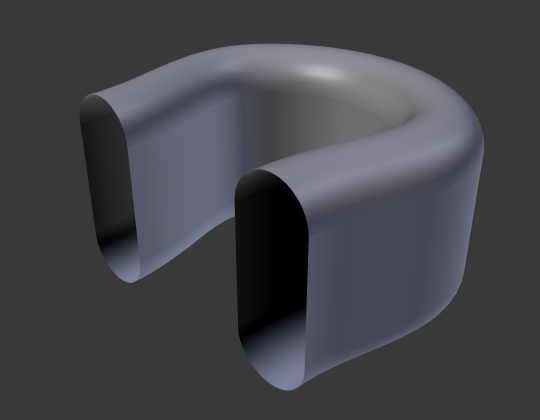
闭合的2D曲线
这可能是最有用的情形了,因为这可以迅速创建一个体积,(默认情况下) 两个平坦且平行的曲面填充在挤出的“墙”两侧。可以通过选择填充模式为两者、前、后或无,来删除其中的一个或两个都删除 。
可选的倒角深度总是在这里创建一个90度的倒角。
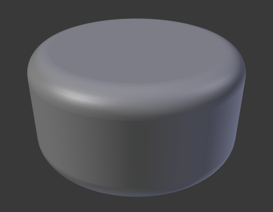
闭合2D曲线,挤出 0.5,倒角深度 0.25 ,倒角分辨率10,填充:两者。
3D 曲线
这时的事实是,曲线是否闭合并不重要——永远无法得到一个带体积的挤出的3D 曲线,就像开放的2D曲线一样只有墙或带子。
但是,3D 曲线还有一个特性:控制点的 倾斜 (见上文)。比如,可以使带子绕曲线扭曲以创建一个莫比乌斯环。
锥化
下面我们用锥化曲线来锥化一个简单的曲线圆挤出物体。添加曲线,然后退出 编辑模式。添加另一个(闭合的曲线,比如圆);将其命名为 “BevelCurve” ,并在第一条曲线 ( 物体数据 选项卡) 的 倒角物体 字段中输入该名称。这样得到了一根管子。在 物体模式 中添加第三条曲线并称之为 “锥化曲线” 。调整左侧控制点, 将其提高约5个单位。
现在回到物体数据选项卡,并在几何面板中编辑第一条曲线的 锥化物体 字段,引用前面命名为 “锥化曲线” 的新锥化曲线。按下回车后,将立即应用锥化,结果如图 设置倒角物体为圆环曲线。 所示。
设置倒角物体为圆环曲线。 | 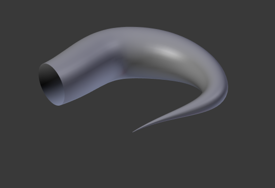 锥化挤出后的曲线。 |
可以看到 锥化曲线 被应用到 挤出物体 。注意观察管道的粗细是如何随着锥化曲线从左至右逐渐缩小到无的。如果锥化曲线位于其局部Y轴下方, 则管道的内侧将变为外侧,这将导致渲染伪影。当然,作为一个艺术家,这可能是你所寻求的效果!
锥化示例1。
在图 锥化示例1。 中,可以清楚地看到左侧的锥化曲线如何影响右侧曲线物体的。在这里,左侧的锥化曲线右侧更靠近物体的水平轴,反映在右侧的物体是就是管道变细。
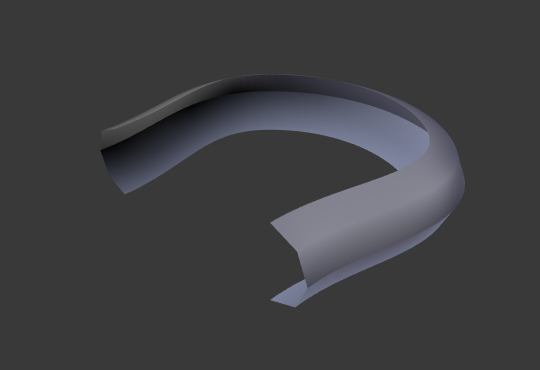
锥化示例2。
在图 锥化示例2。 中,左侧的锥化曲线上的控制点远离原点,从而得到右侧的曲线物体加宽的结果。
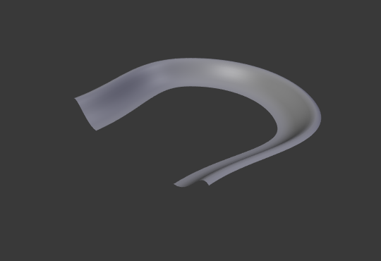
锥化示例3。
在图 锥化示例3。 中对曲线圆环应用了一条更不规则的锥化曲线。
带有 倾斜 的倒角挤出示例。